Thursday 27 November 2014

Animation Techniques


Camera angles and Techniques

This week we looked at the various different camera angles that you can implement. And assessed the different positive and negative effect's that the camera angles can have.

We look at the "One man band" Pixar animation and tried to spot all the different camera angles used.


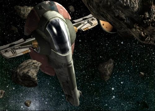
This long shot from the animation establishes that the area the man is in is empty and create the feeling of loneliness. For my animation I want to create this feeling with the asteroid field. I want the viewer to feel that the scene is taking place in desolate space.

Close ups can be used to empathise details, like the violin strings in this image above. I want to use lots of close ups in my animation so that I can display the details of my models.


Point of view, although its hard to show in the image above this is a point of view shot. As I want the viewer of my animation to see through the eyes of the pilot, Im going to implement at least one point of view angle in my animation.

Rule of Thirds
We also learnt about the technique known as the rule of thirds whipsaw is  guideline followed by photographers and visual artists. The basic principle is to divide a scene into nine equal parts., creating s a grid of horizontal and vertical line. Points  of interest sit at the horizontal line that separates the lower third of the scene from the top two-thirds. When the subject is positioned s at the
intersection of two lines they become more visually pleasing to the view. I had learned about this technique in previous study of Film production, and am really keen to try to use it as much as I can within my animation.


12 principles of animation 

Squash and Stretch
 • Arcs
• Anticipation
 • Secondary Action
• Staging 
• Timing and Spacing
• Straight ahead & Pose to Pose 
• Exaggeration
• Follow through and Overlapping
 • Solid Drawing

• Slow in and Slow out 
• Appeal

We learnt about the 12 key principles of animation, out of the list i have highlighted ther ones i feel will be most imposrt in my animation .

Anticipation,

 I tried to think how I could apply this principle to my animation and I though that as my  space ships are going to be chaseing each other i could have them rotaing and banking alot as they navigate the asterpoid feild, to apply the anticaption principle i could have my ship rotate a little amount one way then a complete rotaion in the opposite reaction the diagram below explains what i mean
1st: rotate a little in one direction 2nd: Then rotate fully in opposite direction

Staging

The way i plan to use the staging principle is, i want to direct the audiences focus to key areas of the scene , using the rule of thirds can help me with this. Also since i want the feeling to bee that the ships are chasing each other through tight gaps i will use lots of close-ups and medium shots but try to block out as much as the space background with asteroids to create a claustrophobic feeling.

Timing and Spacing

I plan to apply this principle to my animation by having the ships move in a way that makes them look like there actually flying by having gradual increase in speed rather than sudden one.the flight of the ships should look more natural. By changing scene often as well this should create a feeling of speed and urgency as the ships fly through the asteroid field.

Exaggeration

I can incorporate this principle by having my ships fly through the asteroid in a more exaggerated way by looping round the asteroids and doing flips and spins etc, instead of them just following a straight line. The diagram below explain this


Monday 17 November 2014

Creating Slave I Model


SlaveI 


Having created two really iconic space ships from the star wars universe, i wanted to create a more complex one as my other two model have turned out really well. So i decided to create SlaveI or Boba-fetts ship. I thought this would be a bit more of a challenge because the ship is quite curved. this would also be quite a contrast from both the Tie fighter and Xwing which are ,themselves very angular.


Slave I
Firstly i created a sphere, which I flattened to make the base.
I was able to replicate the optical base of the craft this way, however the poly count of this object was quite high, in future i would perhaps try to optimise the object by reducing the number of faces.


Then using a cube and the Boolean - Difference tool i cut away the bottom so it was flat on one side

Then to create the oval shape, i used the soft select tool which i accessed by double clicking on the scale tool and ticking the corresponding check box, this enabled me to just scale down one of the tips, giving me the desired egg shape below. This tool was a godsend! I discovered it by accident by accidentally double clicking on the scale tool. It was very simple to use and 

Egg/oval shaped base

I then selected these faces and dragged them upwards to add shape to the base.

I then added a sphere and fit it into the crescent area i had just created

i then scaled the sphere so it was longer and thinner. this will be used to create the curved cockpit. I then selected some faces on one end and dragged them out to make the main body part of the ship.


Then using a cube and the Boolean - Difference method i cut off the end of the part of the sphere i had just dragged out. This however incresed my polycount alot. it added lots of edges that were really time consuming to go back and deleted. The shape looked good, however in the future i will use the boolean difference tool with care as it tends to increase my vertices count alot.
Then using the Multicut tool i cut the shape of the cockpit into the sphere, i then selected those edges all around the outline of the cockpit and used the bezel tool to create the frame of the cockpit, i then selected the faces within that outline and extruded them in slightly to create the cockpit. I used the Bezel tool as it saved alot of time compared to cutting the edges again, manually

I then selected a circular pattern of faces on each side of the main body of the ship and scaled them outwards. that created this part of the model.

I then selected the edges around the middle and moves them inwards to create the pronounced centres
The model is now starting to look alot like the ship, i just need to add wings and details


the base of the ship is slightly cut away under the wings to do this i selected the edge you can see highlighted in the picture and scaled it down until it created the shape you see below. 


Cut away for wings


Next i created the struts for the wings, by making a cylinder, rotating it 90 degrees and placing it running through the main body of the ship, i also used more cylinders rotated 45 degrees as the support struts.

Finally to create the wings i added circular cuts  to the cylinder using the Multi-cut tool and control. Then i selected the corresponding face and extruded them to create the wings. I also added some details like the guns on the ship just by using spheres and cylinder. Also i added some details on the underside just to create a more detailed bottom side.
The Finished model


Textureing Slave I

The textures used for this model are again taken from the Internet with the sources provided, In the film Salve I looks really battered and old so i specifically tried to get old, rusty, decaying looking textures. Again I'm reusing some of the textures that i applied to my other models, and will be mostly using the Lambert materiel, as i am aiming for an old, worn look. however the parts in green, and rust brown i wanted to be a bit shiny so used the Blinn material. The cockpit like the xwing and tie fighter are plain black anisotropic.
This texture will be applied to some of the mainbody of the ship and really looks old and worn
source: http://3.bp.blogspot.com/-aUsK5m_AvDI/UFwYXcqbUSI/AAAAAAAACOY/IrUarx-9sB4/s1600/Tileable+eroded+scratch+metal+texture+background+03.jpg


This texture is also going to be used for the main body and looks really good and decayed.
source: http://www.texturepalace.com/gallery/metal/0405/8metal_texture_big_100405.jpg

This texture will be used for the two domes either side of the cockpit
source: http://www.texturepalace.com/metal-rusty-metal-free-stock-textures/

This texture will be used for the wing struts and inside the domes either side of the cockpit
source: http://www.nuinu.su/art/318-fraktaly-yeto-iskusstvo-11-foto.html

this texture will be used for the lip that runs around the outside of the base
source: :http://volpuri.ru/phh/37/rzhavchina_tekstura_rzhavyy_oranzhevyy_poverhnost_shershavyy_prev.jpg


The Finished model

Once i had mapped all the textures using the create UV- planar mapping tool, the final result looked really good. The ship defiantly look aged and worn like i intended and is by far my favourite out of my three models.


Like the other three i created an anisotropic material with a glow affect to simulate the engines and on this model i think it look especially cool.


Wednesday 5 November 2014

Texturing the Tie fighter Model

Textures used


The tie fighter is good when it comes to textures as it only really has two materials, the metal of the ship and the material in the wing segments. Again like the X-wing I got my textures from the internet and even used one of the same texture sources I used for the X wing.
This is the Texture I will use for the the majority of the ship. I will use Maya's colour settings to shift its colour slightly blue though.
Source :http://tiagocomicart.blogspot.co.uk/2013/10/textura-de-prueba-para-la-spaceship.html

This Carbon fibre texture works perfectly for the Wing segments of the Tie fighter.
source: http://textures8.com/wp-content/uploads/2014/08/Carbon-Fiber-Background-4-625x416.jpg
The Tie-Fighter model once textures had been applied.Again like the X-wing all of the textures were the Lambert material apart from the cockpit window which was anisotropic. This is because again i wanted the ship to have a worn look too it, and not be shiny.

Again i used the create UV - Planar mapping tool to correctly orientate the textures, specifically the wing segment textures as they have that distinctive pattern.
Like the X -wing I added a Green anisotropic material with a glow effect to look like the engine
The finished Model, again I'm really happy with how this model turned out and think it looks great

Tuesday 4 November 2014

Making the Tie-fighter Model


Making the Wings

 The second Model I started on was the Tie fighter. This time i imported an image into The view field to get the correct size and shape of the wings.
I then created a cylinder and rotated it 90 degrees and changed the sub divisional axis so that is was hexagonal in shape, then I pulled each edge out until it matched the picture in the viewfinder.
I then selected the edges around the wing and used the Bezel tool to create the type of edge you see in the picture below. I then deleted the image from my view window and decided to model the rest of the Tie-fighter using the pictures along side my Maya window as I did before with my x wing.

I then duplicated the Wing


 I then found out through an example project on the Internet about this feature within the preferences window, when i unchecked this the faces selected move separate when i extruded  them and scaled them down. Source : http://knowledge.autodesk.com/support/maya/learn-explore/caas/CloudHelp/cloudhelp/2015/ENU/Maya/files/Edit-Mesh--Keep-Faces-Together-htm.html

 This then split the wing into 6 faces each with a little boarder around them. Which is exactly what I was trying to achieve.
I then used the vertex option to select the six central vertexes, i then used the scale tool to expand them outwards creating this effect.
I then selected each of the six faces again and extruded them inwards to make the struts of the wing pronounced.


I then Built out the centre part of the wings by creating a cylinder with 6 sub divisional axis and to create a hexagon and then inserted it into the middle of the wing and used the Boolean operation union to join it too the wing. Then just used the extrude tool with the multi -cut tool  to keep adding edges then selecting faces, scaling them then extruding them until i had added enough detail. 

Making the centre cockpit


The next step was to start on the cockpit. To create the cockpit I made a sphere and then lowered the sub divisional axis until it was quite angular. I then rotated the sphere so that it was on its side. This meant was so it would be easier for me to cut out the cockpit window.

Using the Multi-cut tool i cut out the shape of the cockpit window and then selected and deleted edges to create sections of the cockpit window.

I then selected the faces that are going to be the glass of the window and then extruded them inwards. This created the basic shape of the window.

To add detail to the window frame i selected all the central edges and pulled them out. This game the window frame more depth, rather than the flat look it had before


The resulting window

I created this part of the mesh by manipulating one of the faces of the sphere. To do this added extra vertex's using the Multi-cut tool and pulled them out until i had this shape. I did the same on the other side of the sphere. It was really hard to get each side exactly the same and took ages. 


I then extrude that shape outward to create the struts either side


Using the extrude tool i added further detail to the top and back of the model
Now all that was left to do was move the wings down into  place

The finished model